Setting up IE Connectors
Connectors are apps running on Industrial Edge Devices (IE Devices) that translate data between PLCs and Edge Apps. They convert various industrial protocols such as OPC UA, Ethernet IP, or S7 into the standardized MQTT protocol.
- Connectors enable seamless communication between PLCs from different manufacturers and Edge Apps, reducing integration complexity.
- Connectors simplify app development by requiring developers to support only MQTT protocol integration.
When deployed, connectors automatically handle the protocol conversion process:
- Receive data from PLCs in their native protocols.
- Transform data into MQTT format.
- Publish the converted data to an MQTT broker (Databus) on the IE Device.
- IE Apps on the IE Device can subscribe to relevant MQTT topics and process the data.
Choosing your connector
These tutorials will look at the process of configuring the following connectors:
- OPC UA Connector
- Ethernet IP Connector
- S7 Connector
Choose a connector based on your device type and company preferences. All connectors deliver the same result on Industrial Edge. Use the flowchart below for guidance:
The different connectors also have different limitations regarding how many tags can be configured. Refer to their documentation for more information:
Recommended connector for multiple protocols or standards
Siemens recommends using OPC UA Connector for IE devices that require multiple protocols or standards due to its platform independence, robust security features, and scalability. OPC UA Connector supports seamless integration across diverse systems, making it ideal for modern industrial environments. However, using OPC UA Connector may result in higher data traffic.
Connectors provided with Industrial Edge Management
Always refer to the official connector documentation for supported devices.
Industrial Edge Management contains the following connectors free of charge:
| Protocol | Connector application | Supported devices and documentation |
|---|---|---|
| OPC UA | OPC UA Connector | |
| S7 | S7 Connector |
Other compatible Connectivity Suite connectors
Always refer to the official connector documentation for supported devices.
Industrial Edge Management does not contain the following Connectivity Suite connectors, which are available for purchase in the Marketplace for an additional cost:
Connecting a PLC using a Siemens connector
- To connect a device using OPC UA, proceed to Connecting a PLC using OPC UA Connector.
- To connect a device using Ethernet IP, proceed to Connecting a PLC using Ethernet IP Connector.
- To connect a device using S7, proceed to Connecting a PLC using S7 Connector.
- To connect a device using another Siemens connector, follow the installation steps for the specific Siemens connector to complete the setup. The documentation for each connector is listed in the table above Other compatible Connectivity Suite connectors. Then proceed to Creating an asset model.
Connecting a PLC using OPC UA Connector
In this tutorial, use OPC UA Connector to connect a PLC to your Industrial Edge environment.
To connect Industrial Edge to your environment, you need three main components:
- The OPC UA Connector to read data from your PLC and translate it to MQTT.
- The Databus App to run on your IE Device, act as a central data broker, and store data configurations for your individual applications.
- The IIH Essentials App to implement a digital representation of your machine and make the data accessible via a REST-API for further processing.
Two additional apps are used during the process for your convenience:
- The Databus Configurator App in the IEM instance.
- The Common Configurator App to provide a user interface for IIH Essentials and to add data sources to OPC UA Connector.
The figure below highlights the roles of the different applications and components.
Prerequisites for connecting a PLC using OPC UA Connector
Software requirements
- You have completely set up your Industrial Edge environment, including Industrial Edge Hub, Industrial Edge Management, and Industrial Edge Device.
- You have installed the required IE apps on your IE Device, including the OPC UA Connector app.
- You have set up the Databus Configurator app in your IEM.
- You know the communication path of your PLC.
- You have installed TIA Portal.
Hardware Requirements
- A PLC-device which supports data transfer via OPC UA
- A RJ45 Ethernet cable (when using VMware and a virtual IE Device)
Enabling the OPC UA Server in the TIA Portal
TIA Portal is Siemens' engineering software and framework for programming and managing automation devices. Activate the OPC UA server on the TIA Portal to use the OPC UA Connector app on the PLC.
- Open the TIA Portal.
- In the "Device" column, click the PLC you wish to enable. Click "Device Configuration".
- Click "OPC UA" > "Server" > "General".
-
Under "Accessibility of the Server", click the checkbox to "Activate OPC UA server".
-
Click "OPC UA" > "Server" > "Security".
-
Under "Security policies available on the server for the secure channel", click the checkbox for "No security".
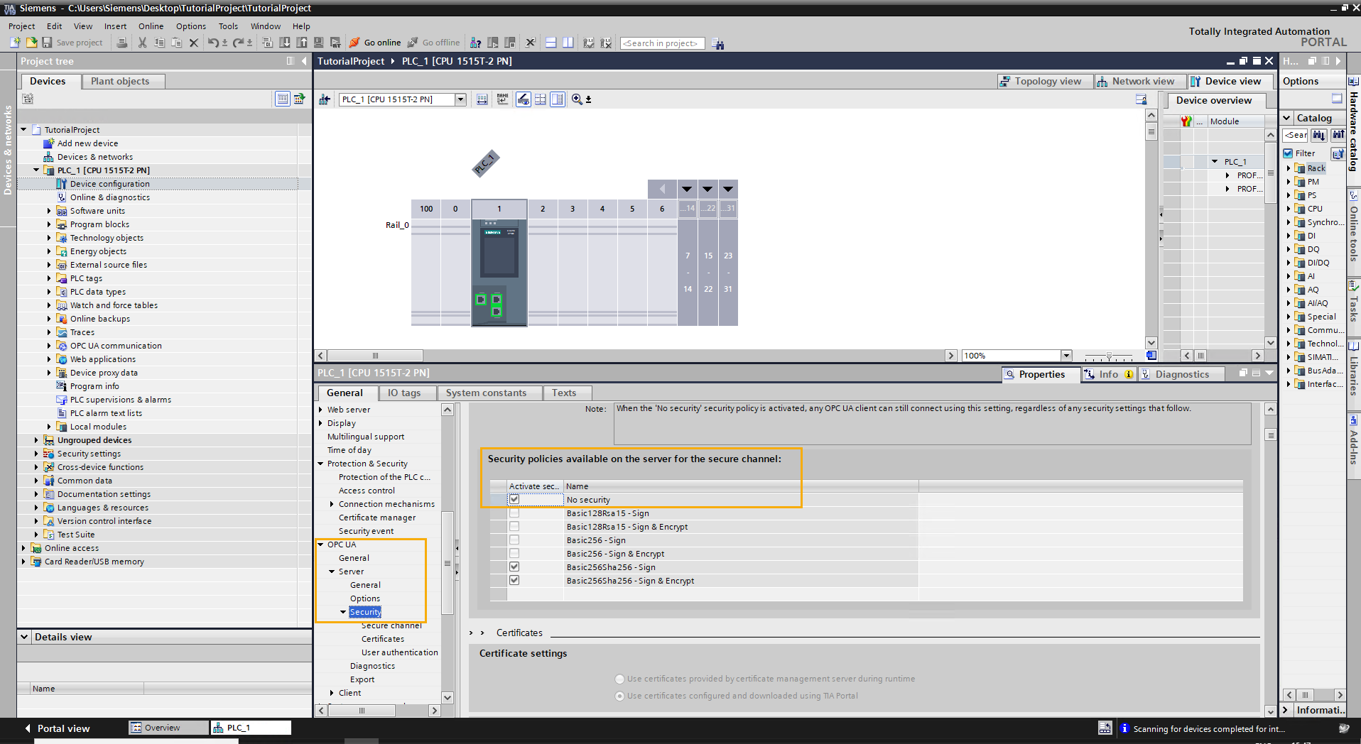
Notice
Using "No Security" for OPC UA Connectors is not recommended for a production environment. Use certificates for cybersecurity best practices.
Configuring the network interfaces for IE Devices to connect to OPC UA Connector
The network interfaces for physical IE Devices were configured as part of the onboarding process. Additional steps are required to allow connections between the PLC and a virtual IE Device.
If you are using a physical IE Device, proceed to Adding your PLC as an OPC UA data source.
To configure a virtual IE Device, follow the conditional steps based on the hypervisor.
Conditional steps
Create a virtual adapter in Hyper-V. Bridge the virtual adapter to the physical adapter on your machine to establish communication between the PLC and the virtual IE Device.
Next, apply the virtual adapter to your virtual IE Device.
Creating and mapping a virtual network adapter
-
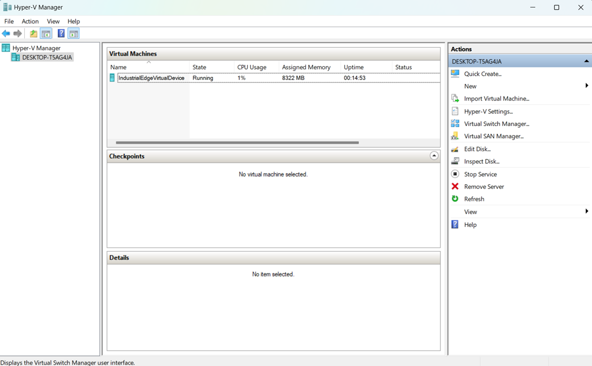
Open Hyper-V. The library contains a virtual machine for the virtual IE Device.
-
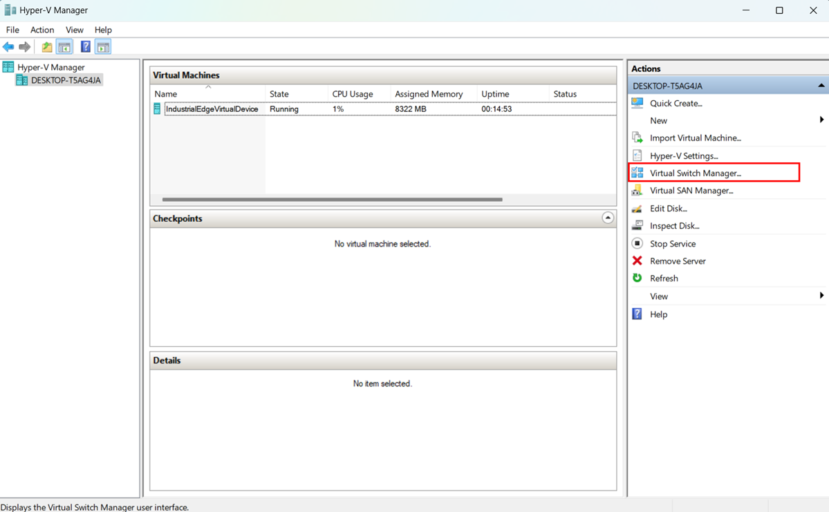
In the right sidebar, click "Virtual Switch Manager”. The "Virtual Switch Manager" window opens.
-
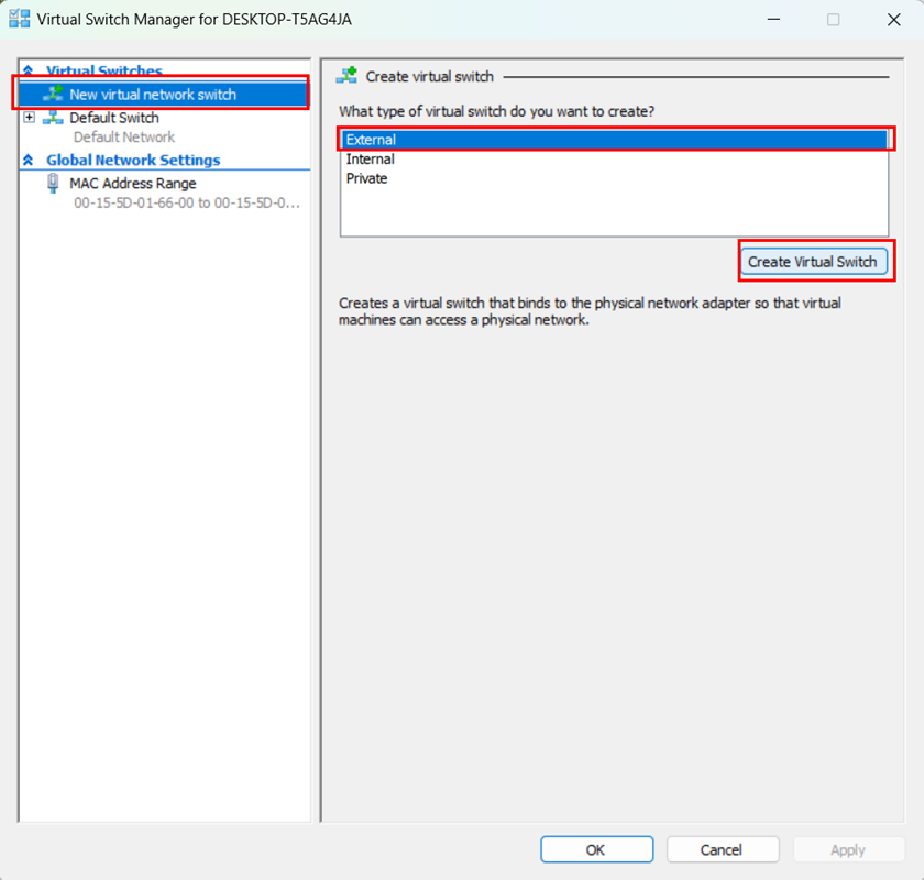
In the left sidebar, select "New Virtual Network Switch”.
- Choose Type: "External".
- Click "Create Virtual Switch".
-
Click "OK".
-
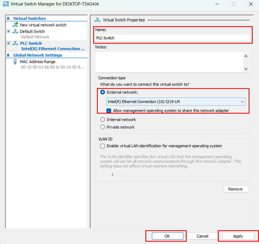
Choose a name for your virtual switch.
- Select "External network". A dropdown menu appears.
- Select the network adapter you want to use.
- Check the box for "Allow management operating system to share this network adapter".
- Click "Apply".
-
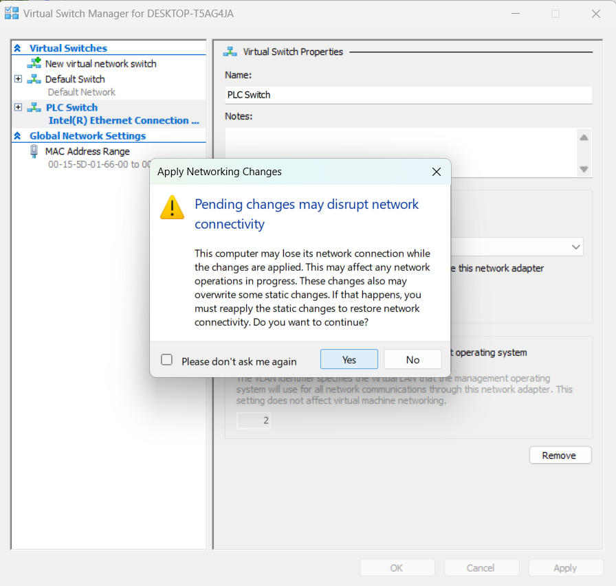
Click "OK".
-
Read the warning message as shown in the figure below. Click "Yes".
Applying the virtual network adapter to the virtual machine
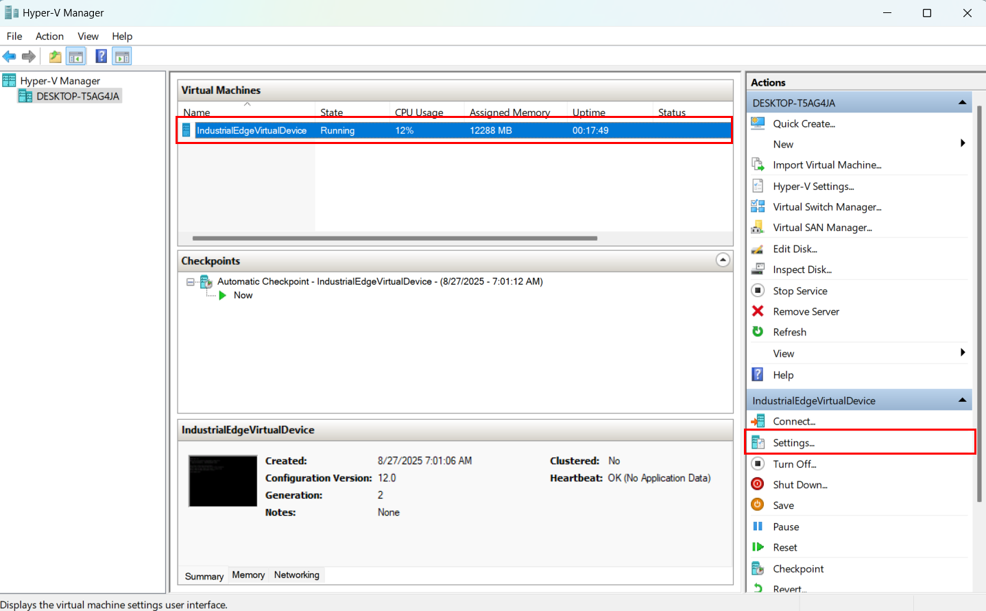
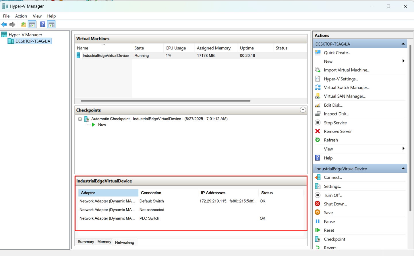
- Select the VM named "IndustrialEdgeVirtualDevice".
-
In the right sidebar, click "Settings". A dropdown menu appears.
-
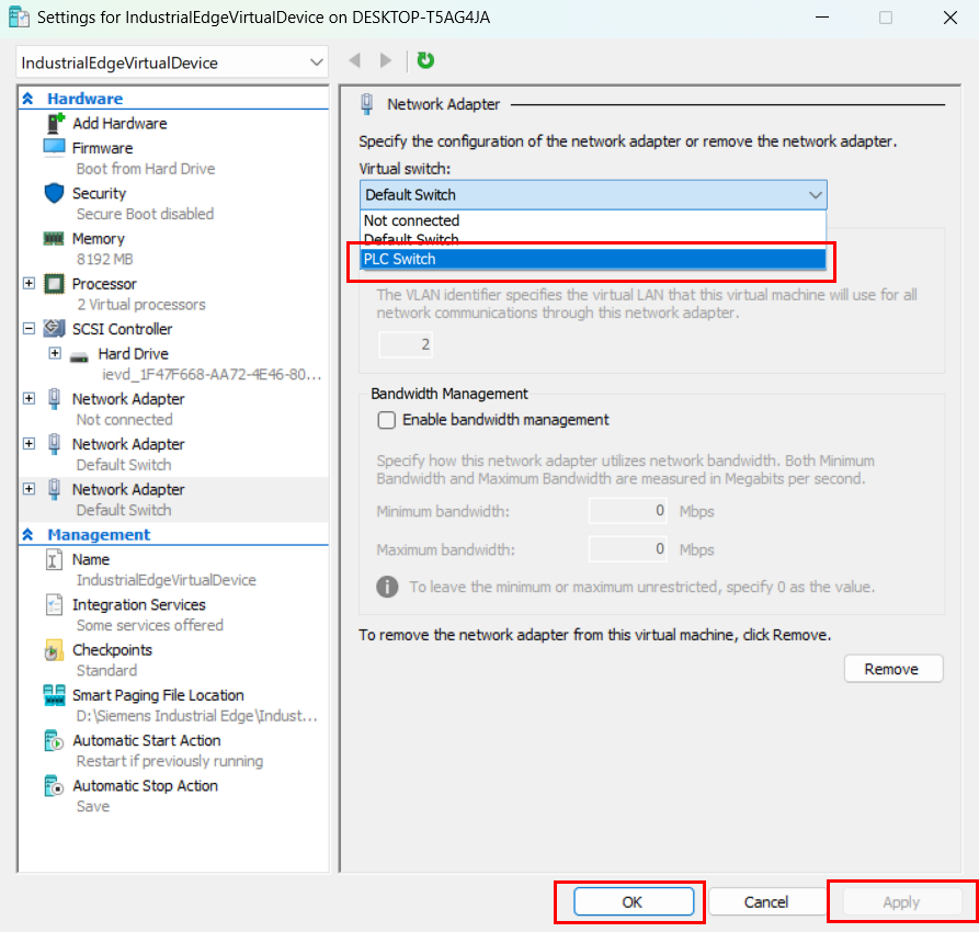
Select the newly created switch.
- Click "Apply."
-
Click "OK".
Hyper-V displays the virtual network adapters when successfully connected.
What's next?
Proceed to Setting up the network connection for the virtual IE Device and OPC UA Connector
Bridging the physical network adapter to the virtual machine
Using an Ethernet cable, bridge the physical network adaptor directly to the virtual machine with VMware.
- Connect the PLC to your laptop using an RJ45 Ethernet cable.
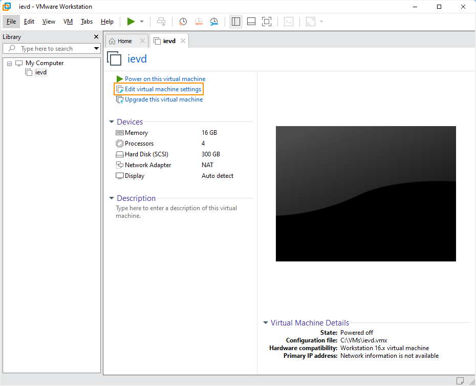
- Open VMware Workstation.
- In the Virtual Machine window, click the Player button in the top left corner.
-
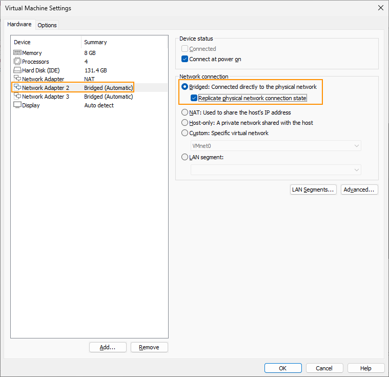
Navigate to "Manage" > "Virtual Machine Settings". The Virtual Machine Settings menu opens.
-
Select "Network Adapter 2".
- Change the network connection setting from "NAT" to "Bridged".
-
Check the box for "Replicate physical network connection state".
-
Click "Configure Adapters". A popup for "Automatic Bridging Settings" appears.
- Check the box for "Intel® Ethernet Connection (10) 12L9-LM". Uncheck all other options.
-
Click "OK" to confirm changes.
NOTICE
The virtual machine's default network adapter is Network Address Translation (NAT), which does not allow external devices to communicate with Industrial Edge Management. Change the adapter type to "Bridged" to allow external devices to communicate with Industrial Edge Management.
What's next?
Proceed to Setting up the network connection for the virtual IE Device and OPC UA Connector
Setting up the network connection for the virtual IE Device and OPC UA Connector
- Open the web browser on your local computer.
- Enter the IP address of the IE Device with the HTTPS protocol, i.e.
https://<ip address>. The screen displays the IE Device UI login screen. - Log in to the Device UI.
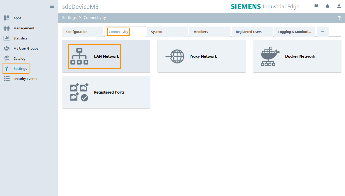
- Click "Settings" from the left navigation pane. The "Settings" page opens.
- Click "Connectivity".
-
Click "LAN Network".
-
Click the pencil icon next to the network adapter "ens32" to modify its network settings.
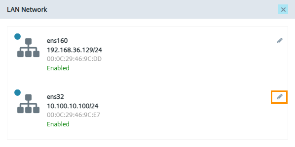
-
Uncheck the "DHCP" checkbox.
-
Enter a static IP address and netmask for the interface. The static IP address should be in the same subnet as the PLC.
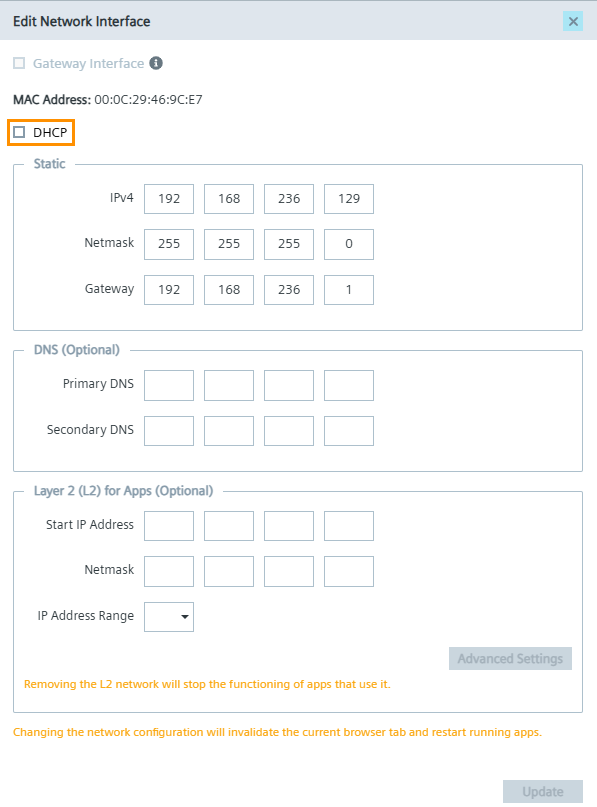
For a PLC with the IP address
192.168.236.127, enter the following values to ensure connectivity between the virtual IE Device and the PLC:- IPv4 (Static IP for the virtual IE Device):
192.168.236.129 - Netmask:
255.255.255.0 - Gateway:
192.168.236.1(if applicable)
- IPv4 (Static IP for the virtual IE Device):
-
Click "Update" to save changes.
Adding your PLC as an OPC UA data source
Use the Common Configurator App to configure an OPC UA data source and set up the OPC UA communication channel to the PLCs for data acquisition.
To add a data source to the OPC UA Connector:
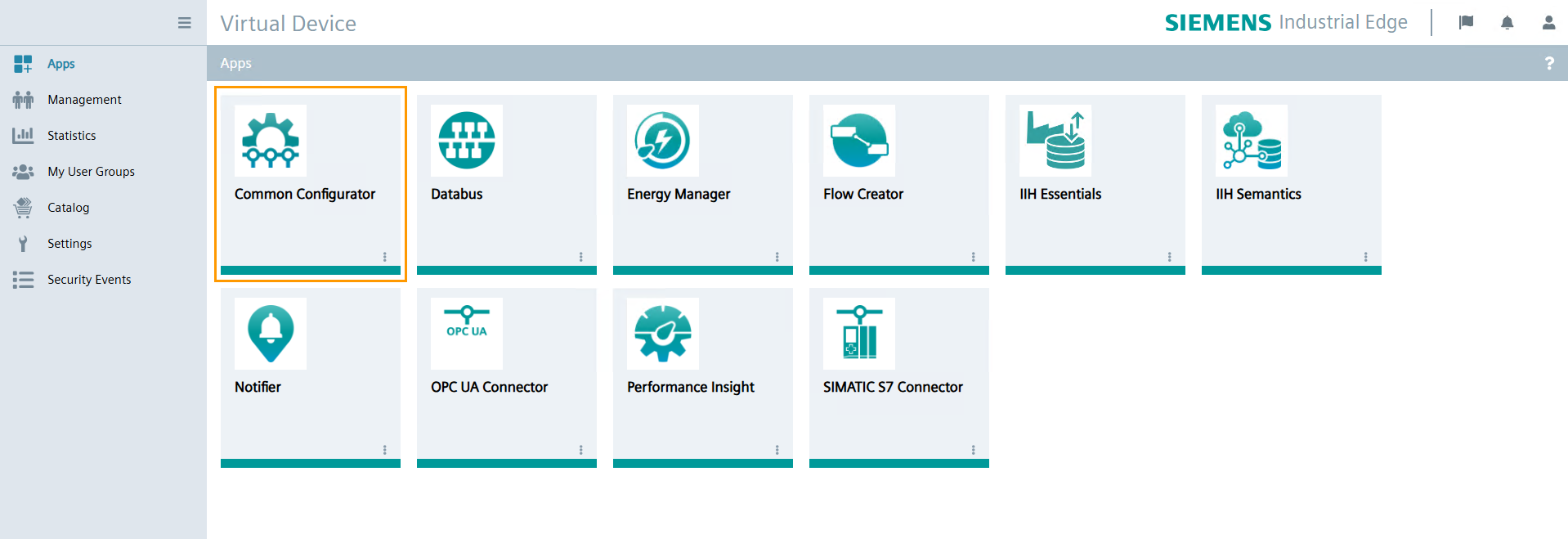
- In the device UI, click "Apps" from the left navigation pane. The "Apps" page opens.
-
Click the "Common Configurator" tile. The "Common Configurator" UI opens.
-
Click "Get Data" from the left navigation pane. A list of configuration apps appears.
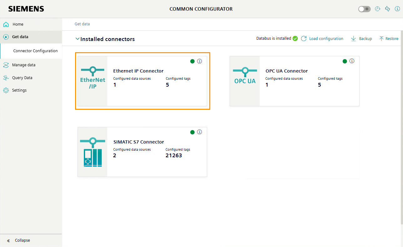
- Click "Connector Configuration". The "Get Data" page opens.
-
Under "Installed Connectors", click "OPC UA Connector".
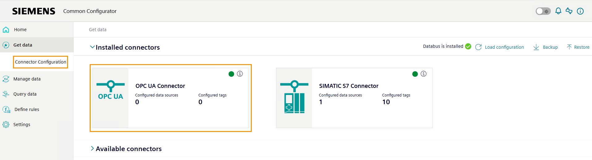
-
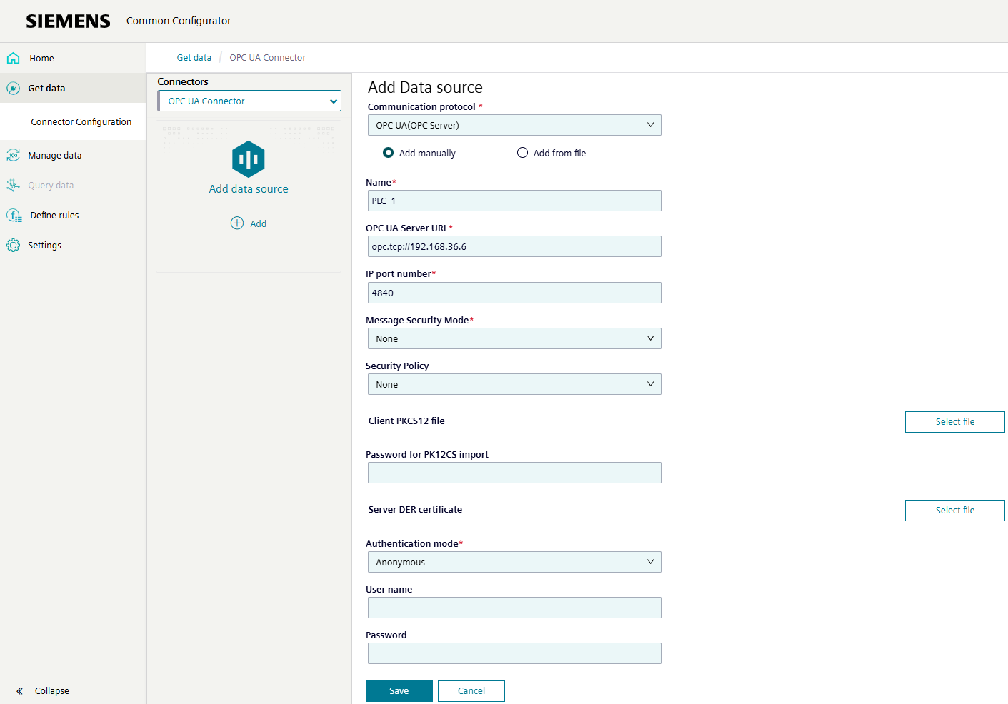
Click "Add". The "Add Data Source" page opens.
NOTE
The OPC UA connector is the interface between the PLC and the IE Device. It must be configured with information about the IP address and other data of your PLC. Once configured, the OPC UA connector can browse the data points of the PLC.
-
Define the following information:
- Communication Protocol: OPC UA (OPC Server)
- Communication Protocol: Select "Add manually"
- Name: Can be freely chosen
- OPC UA Server URL:
opc.tcp://<ip address of PLC> - IP port number:
4840 - Message Security Mode: None
- Security Policy: None
- Authentication mode: Anonymous
NOTICE
This tutorial has not selected any security policies or authentication for testing purposes. Using "No Security" for OPC UA Connectors is not recommended for a production environment. Use certificates for cybersecurity best practices.
More information
More information about the settings is available in the OPC UA Connector documentation.
-
Click "Save". OPC UA Connector activates the configuration.
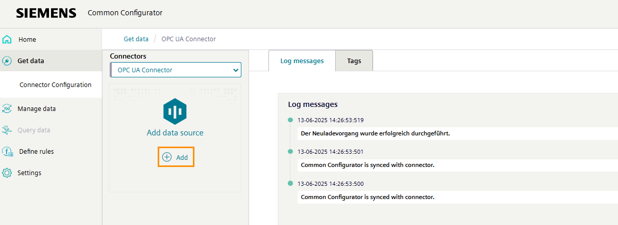
- Click the "Log Messages" tab. The OPC UA Configurator logs open.
-
Check the logs for the message "Connection established to [connector name]." to ensure the connection is properly established.
![Check the logs for the message "Connection established to [connector name]." to ensure the connection is properly established.](assets/06_get_started_connectors/opc_ua_add_data_source_log_message.png)
Configuring the OPC UA connector data source tags
Tags are data points that you wish to fetch from the IE Device. Once the OPC UA Connector data source is created, add and configure the IE Device tags to complete the OPC UA Connector configuration process.
Adding a tag for OPC UA Connector
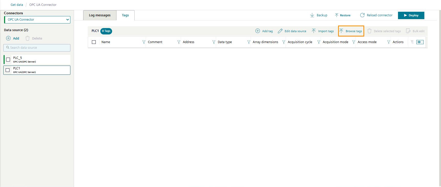
- In the OPC UA Connector page of the Device UI, click the "Tags" tab. The "Tags" page opens.
-
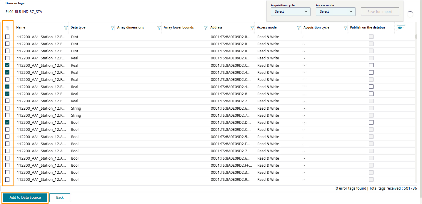
Click "Browse tags".
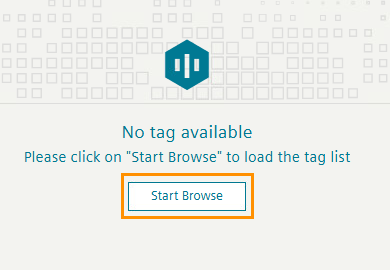
-
Click "Start browse". The OPC UA Connector lists all available tags.
-
Click the checkboxes for the tags you wish to import from the IE Device via the OPC UA Connector.
-
Click "Add to Data Source". OPC UA Connector adds the tags.
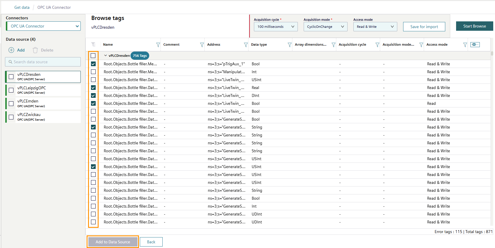
-
To return to the "Tags" tab, click "Back".
Configuring a tag for OPC UA Connector
- In the OPC UA Connector page of the Device UI, click the "Tags" tab. The "Tags" page opens.
-
Click on the pencil icon in the column "Actions" of a tag. The tag becomes editable.
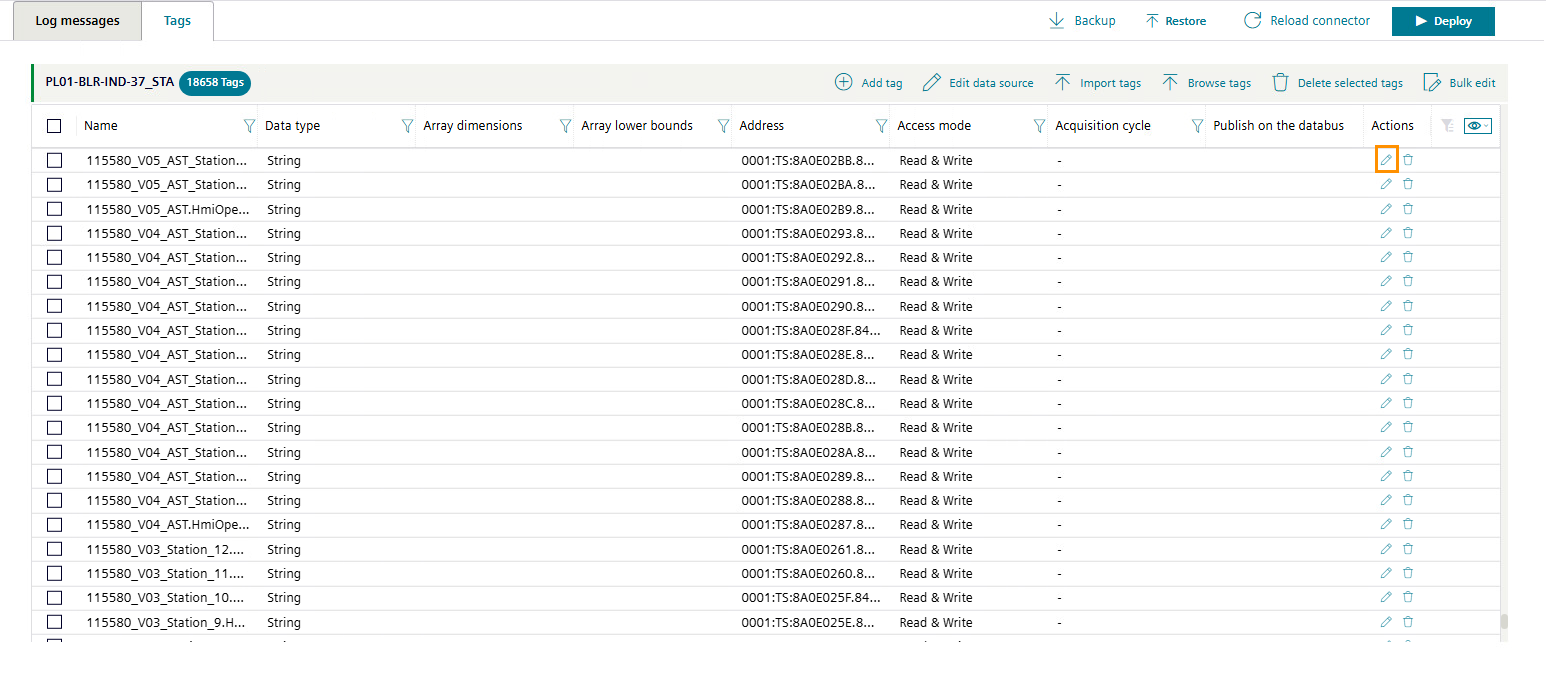
-
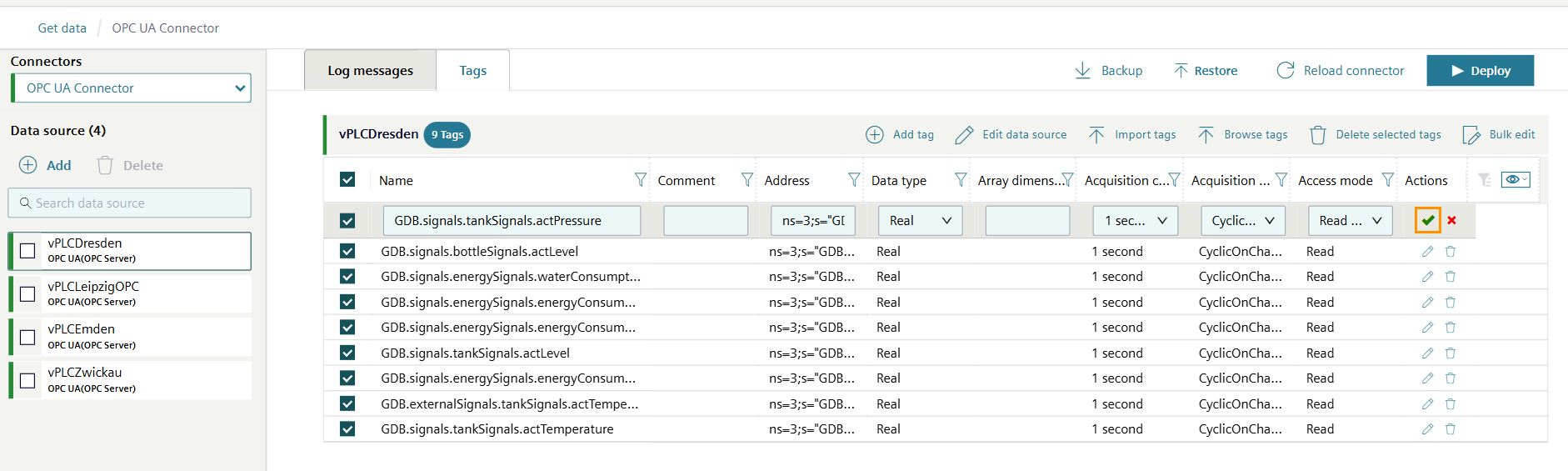
Under "Acquisition cycle", select your preferred acquisition cycle. Siemens recommends using an acquisition cycle of 1 second.
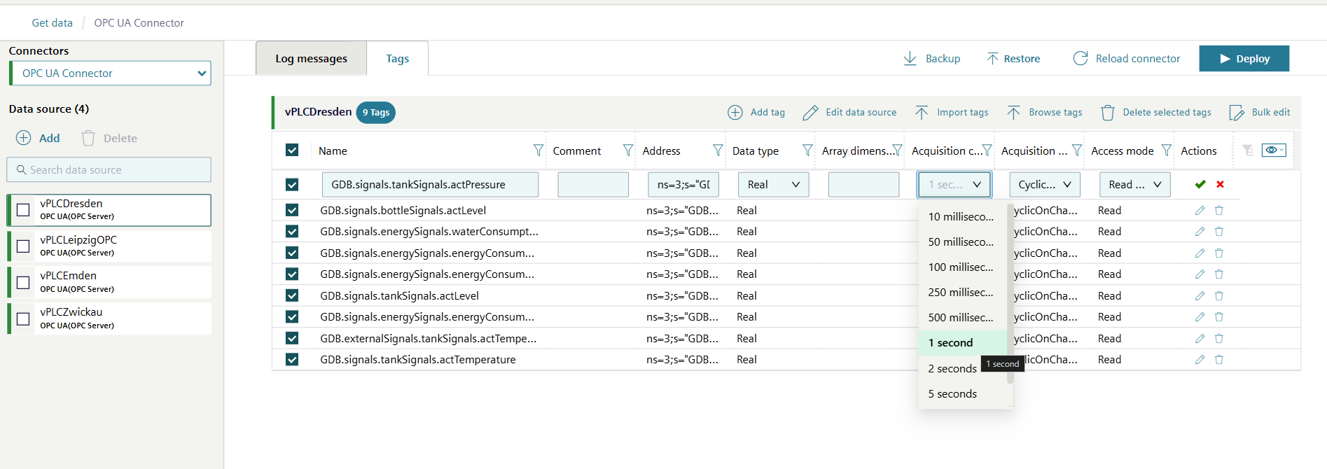
Publish to the Databus
The OPC UA Connector always publishes to the Databus. Therefore the option does not need to be selected like with other connectors.
-
Click the green tick icon to confirm.
-
Repeat steps 2–4 to configure more tags.
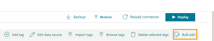
Bulk edit
Use the "Bulk edit" button to apply the same settings to multiple tags at once.
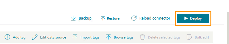
-
Click "Deploy". OPC UA Connector activates the configuration with the selected tags.
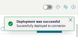
OPC UA Connector displays the pop-up box "Deployment was successful" to indicate the tags were successfully configured.
Validating the outcome of connecting a PLC using OPC UA Connector
Review the log messages for any errors.
You have now connected Industrial Edge to your environment. Proceed to Creating an asset model.
Connecting a PLC using Ethernet IP Connector
In this tutorial, use Ethernet IP Connector to connect a PLC to your Industrial Edge environment.
To connect Industrial Edge to your environment, you need three main components:
- The Ethernet IP Connector to read data from your PLC and translate it to MQTT.
- The Databus App to run on your IE Device, act as a central data broker, and store data configurations for your individual applications.
- The IIH Essentials App to implement a digital representation of your machine and make the data accessible via a REST-API for further processing.
Two additional apps are used during the process for your convenience:
- The Databus Configurator App in the IEM instance.
- The Common Configurator App which provides a UI for IIH Essentials and to add data sources to Ethernet IP Connector.
The figure below highlights the roles of the different applications and components.

Prerequisites for connecting a PLC using Ethernet IP Connector
Software requirements
- You have completely set up your Industrial Edge environment, including Industrial Edge Hub, Industrial Edge Management, and Industrial Edge Device.
- You have installed the required IE apps on your IE Device, including the Ethernet IP Connector app.
- You have set up the Databus Configurator app in your IEM.
- You know the communication path of your PLC.
NOTE
For Allen-Bradley PLCs by Rockwell, the communication path can be read from the config screen of the Rockwell Engineering Tool Studio 5000. For information about how to set the communication path for other PLCs, refer to the Ethernet IP Connector Documentation.
Hardware requirements
- A PLC device, which supports data transfer via the Ethernet IP protocol, such as:
- Allen-Bradley ControlLogix
- Allen-Bradley CompactLogix
- Allen-Bradley MicroLogics
- Allen-Bradley SLC
- Omron CJ1 Series PLCs
- Omron CJ2 Series PLCs
- Omron CS1 Series PLCs
- RJ45 Ethernet cable (When using VMware and a virtual IE Device)
Configuring the network interfaces for IE Devices to connect to Ethernet IP Connector
The network interfaces for physical IE Devices were configured as part of the onboarding process. Additional steps are required to allow connections between the PLC and a virtual IE Device.
If you are using a physical IE Device, proceed to Adding your PLC as an Ethernet IP data source.
To configure a virtual IE Device, follow the conditional steps based on the hypervisor.
Conditional steps
Create a virtual adapter in Hyper-V. Bridge the virtual adapter to the physical adapter on your machine to establish communication between the PLC and the virtual IE Device.
Next, apply the virtual adapter to your virtual IE Device.
Creating and mapping a virtual network adapter
-
Open Hyper-V. The library contains a virtual machine for your virtual IE Device.
-
In the right sidebar, click "Virtual Switch Manager”. The Virtual Switch Manager window opens.
-
In the left sidebar, select "New Virtual Network Switch”.
- Choose Type: "External".
- Click "Create Virtual Switch".
-
Click "OK".
-
Choose a name for your virtual switch.
- Select "External Network". A dropdown menu appears.
- Select the network adapter you want to use.
- Check the box for "Allow management operating system to share this network adapter".
- Click "Apply".
-
Click "OK".
-
Read the warning message as shown in the figure below. Click "Yes".
Applying the virtual network adapter to the virtual machine
- Select the VM named "IndustrialEdgeVirtualDevice".
-
In the right sidebar, click "Settings". A dropdown menu appears.
-
Select the newly created switch.
- Click "Apply."
-
Click "OK".
Hyper-V displays the virtual network adapters when successfully connected.
What's next?
Proceed to Setting up the network connection for the virtual IE Device and Ethernet IP Connector.
Using an Ethernet cable, bridge the physical network adaptor directly to the virtual machine with VMware.
- Connect the PLC to your laptop using an RJ45 Ethernet cable.
- Open VMware Workstation.
- In the Virtual Machine window, click the Player button in the top left corner.
-
Navigate to "Manage > Virtual Machine Settings". The Virtual Machine Settings menu opens.
-
Select "Network Adapter 2".
- Change the network connection setting from "NAT" to "Bridged".
-
Check the box for "Replicate physical network connection state".
-
Click "Configure Adapters". A popup for "Automatic Bridging Settings" appears.
- Check the box for "Intel® Ethernet Connection (10) 12L9-LM". Uncheck all other options.
-
Click "OK" to confirm changes.
NOTICE
The virtual machine's default network adapter is Network Address Translation (NAT), which does not allow external devices to communicate with Industrial Edge Management. Change the adapter type to "Bridged" to allow external devices to communicate with Industrial Edge Management.
What's next?
Proceed to Setting up the network connection for the virtual IE Device and Ethernet IP Connector.
Setting up the network connection for the virtual IE Device and Ethernet IP Connector
- Open the web browser on your local computer.
- Enter the IP address of the IE Device with the HTTPS protocol, i.e.
https://<ip address>. The screen displays the IE Device UI login screen. - Log in to the Device UI.
- Click "Settings" from the left navigation pane. The "Settings" page opens.
- Click "Connectivity".
-
Click "LAN Network".
-
Click the pencil icon next to the network adapter "ens32" to modify its network settings.
-
Uncheck the "DHCP" checkbox.
-
Enter a static IP address and netmask for the interface. The static IP address should be in the same subnet as the PLC.
For a PLC with the IP address
192.168.236.127, enter the following values to ensure connectivity between the virtual IE Device and the PLC:- IPv4 (Static IP for the Industrial Edge Virtual Device):
192.168.236.129 - Netmask:
255.255.255.0 - Gateway:
192.168.236.1(if applicable)
- IPv4 (Static IP for the Industrial Edge Virtual Device):
-
Click "Update" to save changes.
Adding your PLC as an Ethernet IP data source
Use the Common Configurator App to configure an Ethernet IP Connector data source and set up the Ethernet IP communication channel to the PLCs for data acquisition.
To add a data source to the Ethernet IP Connector:
- In the device UI, click "Apps" from the left navigation pane. The "Apps" page opens.
-
Click the "Common Configurator" tile. The "Common Configurator" UI opens.
-
Click "Get Data" from the left navigation pane. A list of configuration apps appears.
- Click "Connector Configuration". The "Get Data" page opens.
-
Under "Installed Connectors", select "Ethernet IP Connector".
-
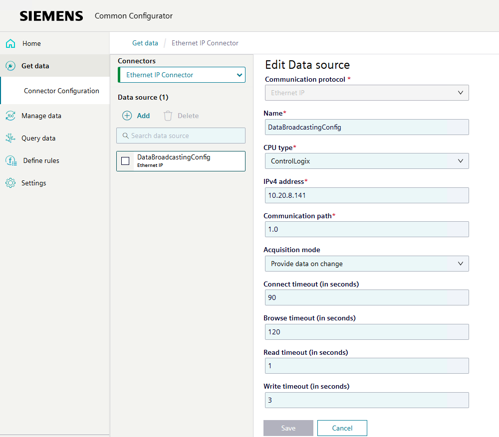
Click "Add". The "Add Data Source" page opens.

NOTE
The Ethernet IP Connector is the interface between the PLC and the IE Device. It must be configured with information about the IP address and other data of your PLC. Once configured, the Ethernet IP Connector can browse the data points of the PLC.
-
Define the following information:
- Communication Protocol: Ethernet IP
- Communication Protocol: Select "Add manually"
- Name: Can be freely chosen
- CPU type: Select the type of PLC you are connecting with
- IPv4 address: Enter the IP address of the PLC
- Communication path: Enter the communication path of your PLC.
More information
More information about the settings is available in the Ethernet IP Connector documentation.
-
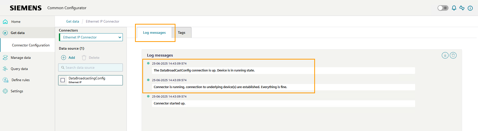
Click "Save". Ethernet IP Connector activates the configuration.
- Click the "Log Messages" tab. The Ethernet IP Connector logs open.
-
Check the logs for the following messages to ensure the connection is properly established:
- The [Name of Configuration] connection is up. Device is in running state.
- Connector is running, connections to underlying device(s) are established. Everything is fine.
Configuring the Ethernet IP Connector data source tags
Tags are data points that you wish to fetch from the IE Device. Once the Ethernet IP Connector data source is created, add and configure the IE Device tags to complete the Ethernet IP Connector configuration process.
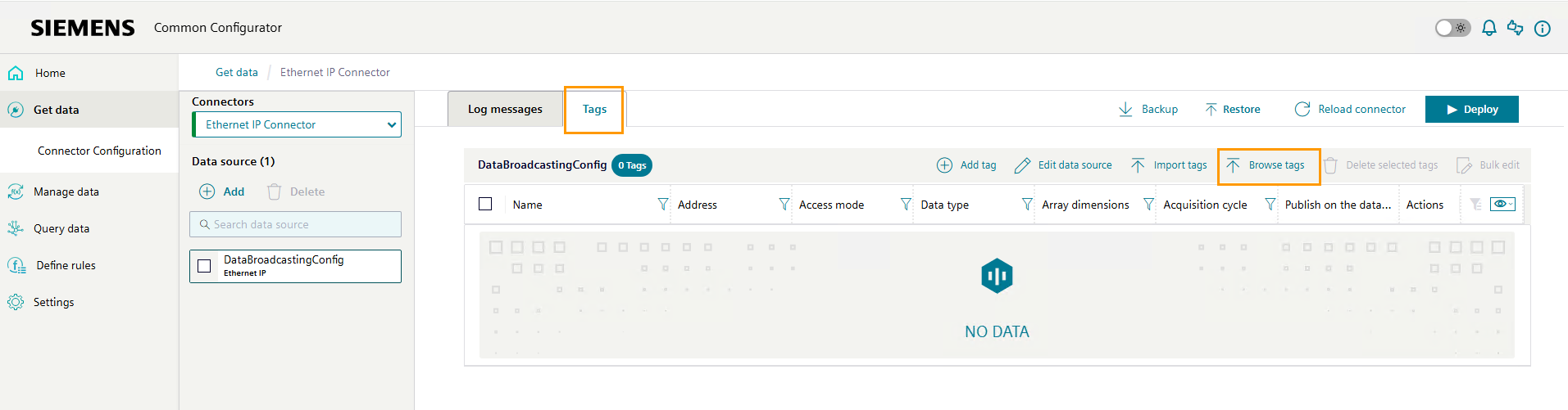
Adding a tag for Ethernet IP Connector
- In the Ethernet IP Connector page of the Device UI, click the "Tags" tab. The "Tags" page opens.
-
Click "Browse tags".
-
Click "Start browse". The Ethernet IP Connector lists all available tags.
-
Click the checkboxes for the tags you wish to import from the IE Device via the Ethernet IP Connector.
-
Click "Add to Data Source". Ethernet IP Connector adds the tags.
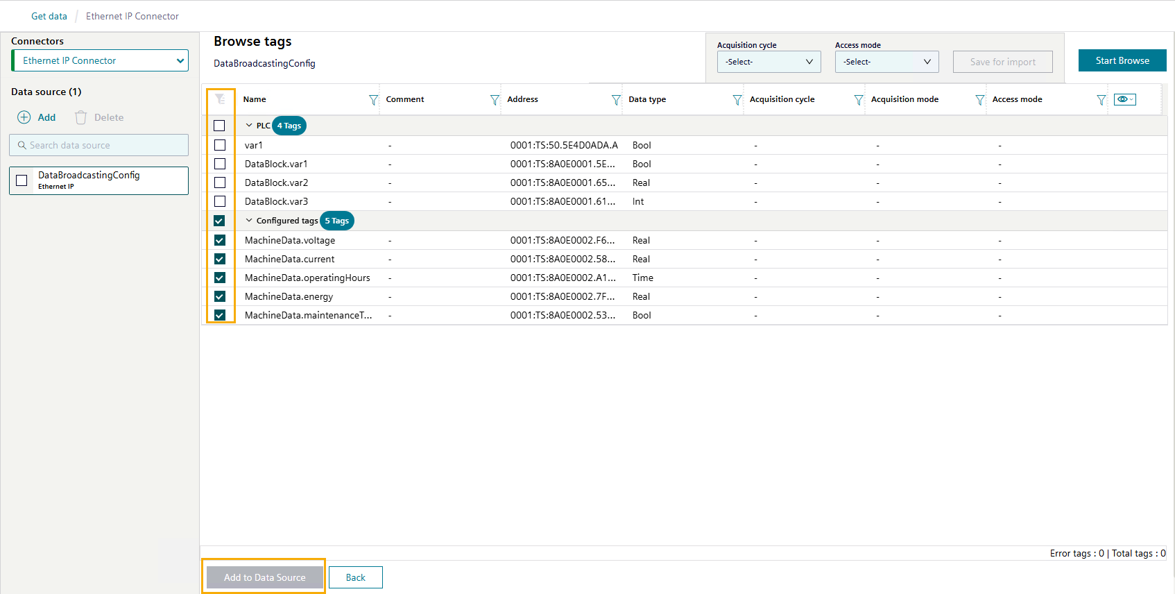
-
To return to the "Tags" tab, click "Back".
Configuring a tag for Ethernet IP Connector
- In the Ethernet IP Connector page of the Device UI, click the "Tags" tab. The "Tags" page opens.
-
Click on the pencil icon in the column "Actions" of a tag. The tag becomes editable.
-
Under "Acquisition cycle", select your preferred acquisition cycle. Siemens recommends using an acquisition cycle of 1 second.
-
Check the "Publish on the Databus" checkbox.
-
Click the green tick icon to confirm.
-
Repeat steps 2–5 to configure more tags.
Bulk edit
Use the "Bulk edit" button to apply the same settings to multiple tags at once.
-
Click "Deploy". Ethernet IP Connector activates the configuration with the selected tags.
Ethernet IP Connector displays the pop-up box "Deployment was successful" to indicate the tags were successfully configured.
Validating the outcome of connecting a PLC using Ethernet IP Connector
Review the log messages for any errors.
You have now connected Industrial Edge to your environment. Proceed to Creating an asset model.
Connecting a PLC using S7 Connector
In this tutorial, use S7 Connector to connect a PLC to your Industrial Edge environment.
To connect Industrial Edge to your environment, you need three main components:
- The SIMATIC S7 Connector to read data from your PLC and translate it to MQTT.
- The Databus App to run on your IE Device and act as a central data broker and stores data configurations for your individual applications.
- The IIH Essentials App to implement a digital representation of your machine and make the data accessible via a REST-API for further processing.
Two additional apps are used during the process for your convenience:
- The Databus Configurator App in the IEM instance.
- The Common Configurator App which provides a UI for IIH Essentials and to add data sources to S7 Connector.
The figure below highlights the roles of the different applications and components.
Prerequisites for connecting a PLC using S7 Connector
Software requirements
- You have completely set up your Industrial Edge environment, including Industrial Edge Hub, Industrial Edge Management, and Industrial Edge Device.
- You have installed the required IE apps on your IE Device, including the Ethernet IP Connector app.
- You have set up the Databus Configurator app in your IEM.
- You know the communication path of your PLC.
Hardware requirements
- A device which supports data transfer via the S7 protocol, such as:
- SIMATIC S7-300
- SIMATIC S7-400
- SIMATIC S7-1200
- SIMATIC S7-1500
Here we are showcasing the S7 Optimized protocol, which only is supported by S7-1200 and S7-1500.
Configuring the network interfaces for IE Devices to connect to S7 Connector
The network interfaces for physical IE Devices were configured as part of the onboarding process. Additional steps are required to allow connections between the PLC and a virtual IE Device.
If you are using a physical IE Device, proceed to Adding your PLC as an S7 data source.
To configure a virtual IE Device, follow the conditional steps based on the hypervisor.
Conditional steps
Create a virtual adapter in Hyper-V. Bridge the virtual adapter to the physical adapter on your machine to establish communication between the PLC and the virtual IE Device.
Next, apply the virtual adapter to your virtual IE Device.
Creating and mapping a virtual network adapter
-
Open Hyper-V. The library contains a virtual machine for your IEvD.
-
In the right sidebar, click "Virtual Switch Manager”. The Virtual Switch Manager window opens.
-
In the left sidebar, select "New Virtual Network Switch”.
- Choose Type: "External".
- Click "Create Virtual Switch".
-
Click "OK".
-
Choose a name for your virtual switch.
- Select "External network". A dropdown menu appears.
- Select the network adapter you want to use.
- Check the box for "Allow management operating system to share this network adapter".
- Click "Apply".
-
Click "OK".
-
Read the warning message as shown in the figure below. Click "Yes".
Applying the virtual network adapter to the virtual machine
- Select the VM named "IndustrialEdgeVirtualDevice".
-
In the right sidebar, click "Settings". A dropdown menu appears.
-
Select the newly created switch.
- Click "Apply."
-
Click "OK".
Hyper-V displays the virtual network adapters when successfully connected.
What's next?
Proceed to Setting up the network connection for the virtual IE Device and S7 Connector.
Using an Ethernet cable, bridge the physical network adaptor directly to the virtual machine with VMware.
- Connect the PLC to your laptop using an RJ45 Ethernet cable.
- Open VMware Workstation.
- In the Virtual Machine window, click the Player button in the top left corner.
-
Navigate to "Manage > Virtual Machine Settings". The Virtual Machine Settings menu opens.
-
Select "Network Adapter 2".
- Change the network connection setting from "NAT" to "Bridged".
-
Check the box for "Replicate physical network connection state".
-
Click "Configure Adapters". A popup for "Automatic Bridging Settings" appears.
- Check the box for "Intel® Ethernet Connection (10) 12L9-LM". Uncheck all other options.
-
Click "OK" to confirm changes.
NOTICE
The virtual machine's default network adapter is Network Address Translation (NAT), which does not allow external devices to communicate with Industrial Edge Management. Change the adapter type to "Bridged" to allow external devices to communicate with Industrial Edge Management.
What's next?
Proceed to Setting up the network connection for the virtual IE Device and S7 Connector.
Setting up the network connection for the virtual IE Device and S7 Connector
- Open the web browser on your local computer.
- Enter the IP address of the IE Device with the HTTPS protocol, i.e.
https://<ip address>. The screen displays the IE Device UI login screen. - Log in to the Device UI.
- Click "Settings" from the left navigation pane. The "Settings" page opens.
- Click "Connectivity".
-
Click "LAN Network".
-
Click on the pencil icon next to the network adapter "ens32" to modify its network settings.
-
Uncheck the "DHCP" checkbox.
-
Enter a static IP address and netmask for the interface. The static IP address should be in the same subnet as the PLC.
For a PLC with the IP address
192.168.236.127, enter the following values to ensure connectivity between the virtual IE Device and the PLC:- IPv4 (Static IP for the virtual IE Device):
192.168.236.129 - Netmask:
255.255.255.0 - Gateway:
192.168.236.1(if applicable)
- IPv4 (Static IP for the virtual IE Device):
-
Click "Update" to save changes.
Adding your PLC as an S7 data source
Use the Common Configurator App to configure an Ethernet IP Connector data source and set up the Ethernet IP communication channel to the PLCs for data acquisition.
To add a data source to the Ethernet IP Connector:
- In the device UI, click "Apps" from the left navigation pane. The "Apps" page opens.
-
Click the "Common Configurator" tile. The "Common Configurator" UI opens.
-
Click "Get Data" from the left navigation pane. A list of configuration apps appears.
- Click "Connector Configuration". The "Get Data" page opens.
-
Under "Installed Connectors", select "S7 Connector".
-
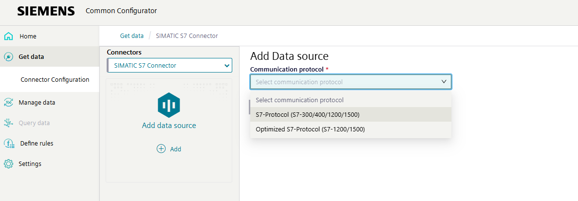
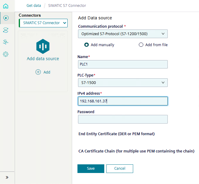
Click "Add". The "Add Data Source" page opens.
NOTE
The S7 connector is the interface between the PLC and the IE Device. It must be configured with information about the IP address and other data of your PLC. Once configured, the S7 connector is able to browse the data points of the PLC.
-
Select the protocol "Optimized S7-Protocol".
-
Define the following information:
- Communication Protocol: Optimized S7-Protocol
- Communication Protocol: Select "Add manually"
- Name: Can be freely chosen
- PLC-Type: Choose the hardware you are using
- IPv4 address: Enter the IP address of the PLC
- Password: If required, enter the corresponding password for connecting to the PLC.
- Certificate files: If required, add the corresponding certificate files.
More information
More information about the settings is available in the S7 Connector documentation.
-
Click "Save" to activate the configuration.
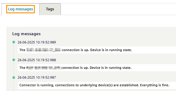
- Click the "Log Messages" tab. The S7 Connector logs open.
-
Check the logs for the following messages to ensure the connection is properly established:
- The [Name of Configuration] connection is up. Device is in running state.
- Connector is running, connections to underlying device(s) are established. Everything is fine.
Configuring the S7 Connector data source tags
Tags are data points that you wish to fetch from the IE Device. Once the S7 Connector data source is created, add and configure the IE Device tags to complete the S7 Connector configuration process.
Adding a tag to S7 Connector
- In the Ethernet IP Connector page of the Device UI, click the "Tags" tab. The "Tags" page opens.
-
Click "Browse tags".
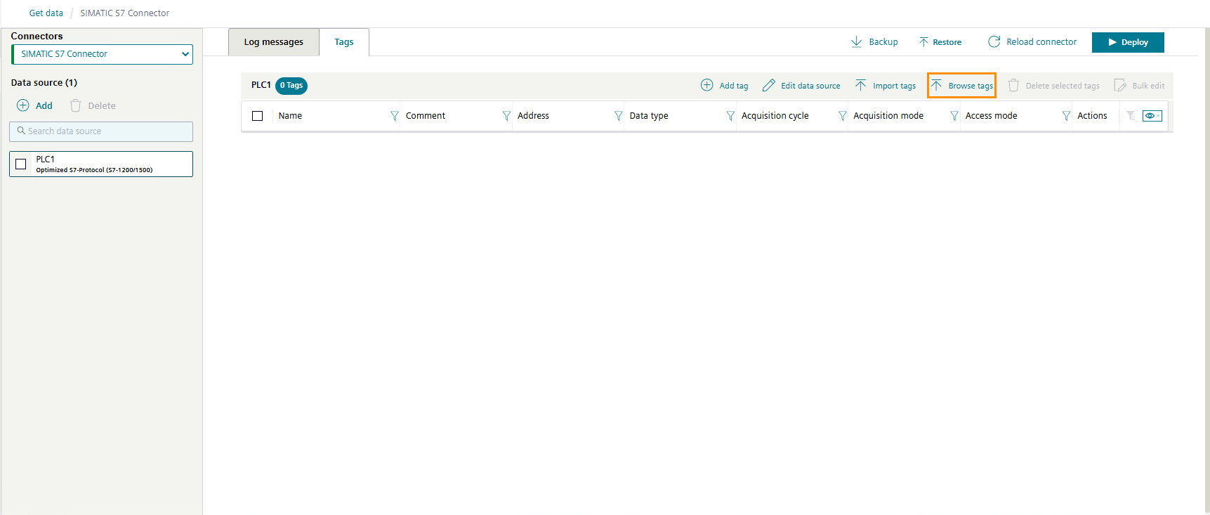
-
Click "Start browse". The S7 Connector lists all available tags.
-
Click the checkboxes for the tags you wish to import from the IE Device via the S7 Connector.
-
Click "Add to Data Source".
-
To return to the "Tags" tab, click "Back".
Configuring a tag for S7 Connector
- In the S7 Connector page of the Device UI, click the "Tags" tab. The "Tags" page opens.
-
Click on the pencil icon in the column "Actions" of a tag. The tag becomes editable.
-
Under "Acquisition cycle", select your preferred acquisition cycle. Siemens recommends using an acquisition cycle of 1 second.
-
Check the "Publish on the Databus" checkbox.
-
Click the green tick icon to confirm.
-
Repeat steps 2–5 to configure more tags.
Bulk edit
Use the "Bulk edit" button to apply the same settings to multiple tags at once.
-
Click "Deploy". S7 Connector activates the configuration with the selected tags.
S7 displays the pop-up box "Deployment was successful" to indicate the tags were successfully configured.
Validating the outcome of connecting a PLC using S7 Connector
Review the log messages for any errors.
You have now connected Industrial Edge to your environment. Proceed to Creating an asset model.
Creating an asset model
Tags are data points that are fetched from the IE Device. Connector apps configure and deploy tags. Before tags can be used by other IE Apps, first collect and store tags in an IIH Essentials asset model.
Industrial Edge uses assets as the main modeling objects to recreate your system structure and to add corresponding attributes. Assets can describe a base class (e.g. Device, MotionDevice, Robot) or a specific asset type for a product line or product model (e.g. Simatic1500SeriesController). Asset models describes an asset independent of the use case.
Attributes are the data members of assets and aspects. IIH Essentials lists the attributes of an asset or aspect in the "Attributes" tab. Attributes can be created specifically for an instance or can be inherited from the asset type or aspect type.
To use asset models, create the asset model in IIH Essentials and define the tags for the asset.
Defining the asset
- Open the web browser on your local computer.
- Enter the IP address of the IE Device with the HTTPS protocol, i.e.
https://<ip address>. The screen displays the IE Device UI login screen. - Log in to the Device UI.
-
Click the "IIH Essentials" tile. The "IIH Essentials" UI opens.
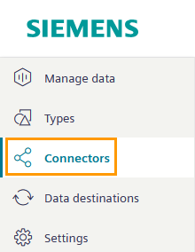
-
Click "Connectors" from the left navigation pane. A list of connectors appears.
-
Select your connector from the list. Ensure the connector is "Active" and "Connected".
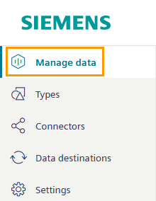
-
Click "Manage data" from the left navigation pane. The "Manage data" page opens.
-
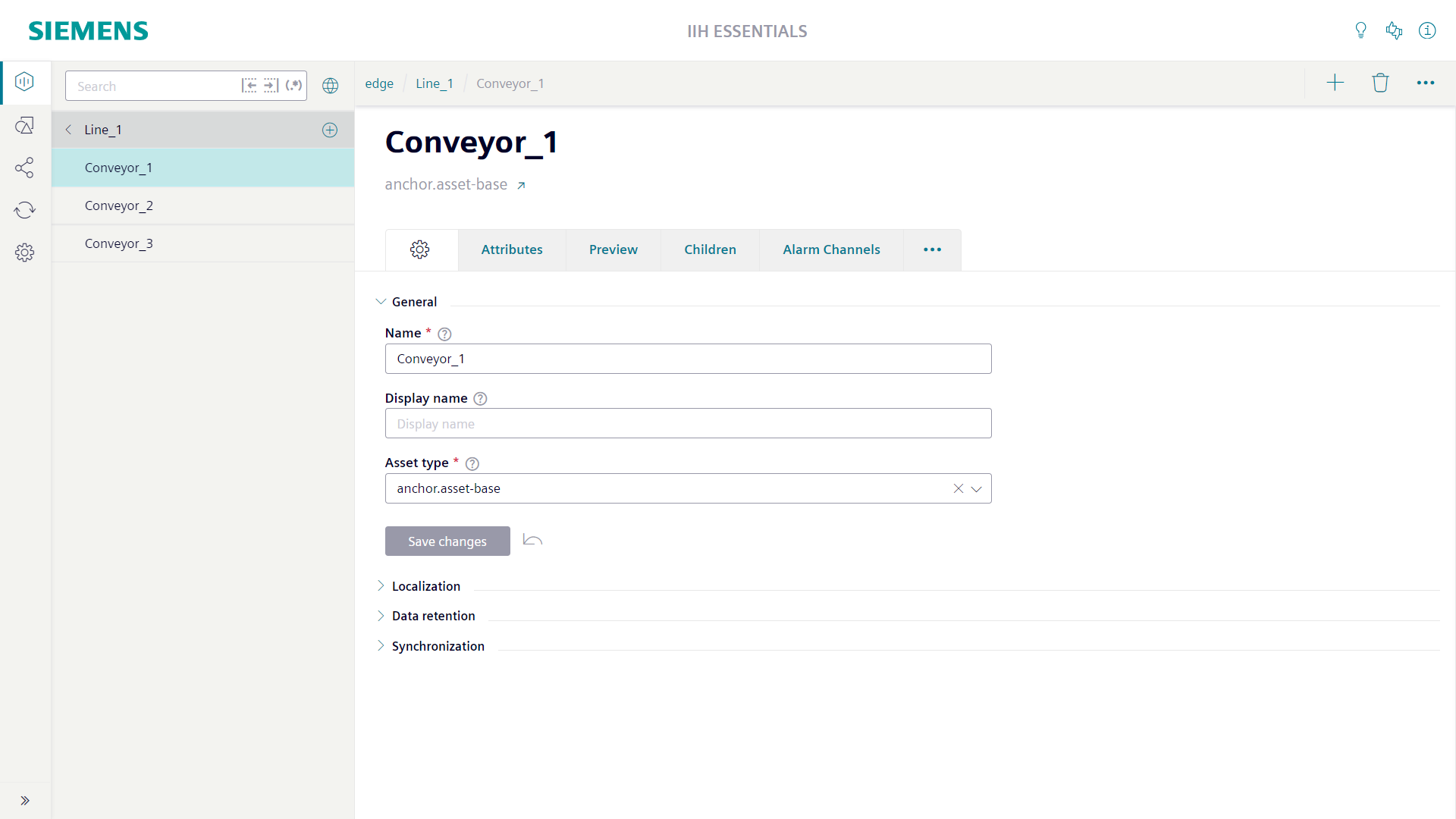
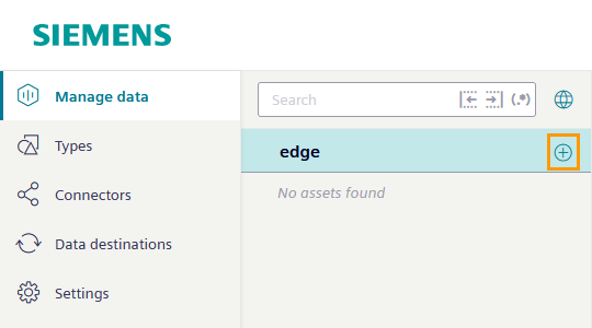
Click the "+" icon next to the listed IE Device you wish to create a new asset from.
-
Provide the asset with a name and display name.
- Select
anchor.asset-baseas the asset type. - Click "Save changes". IIH Essentials creates the asset.
Defining the required tags for the asset
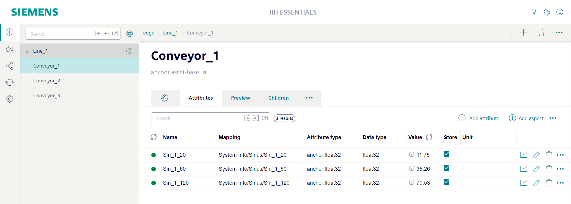
Once the asset is created, define the tags for the asset.
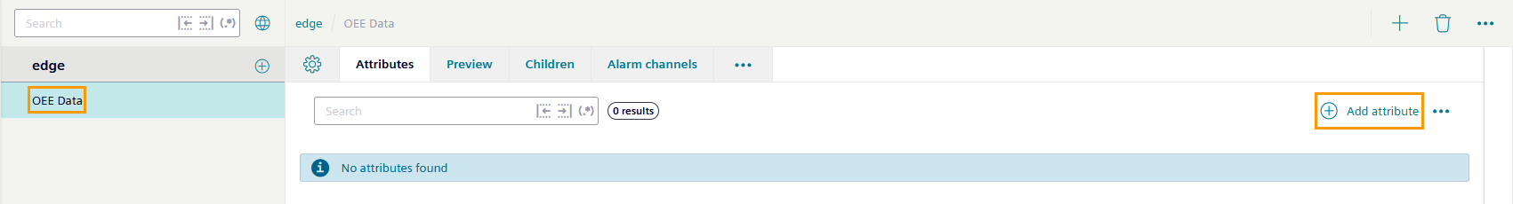
- Select the asset from the tree.
-
Click "Add attribute". The "Add attribute" page opens.
-
Under "Source type", select
Connector. IIH Essentials lists the available connectors.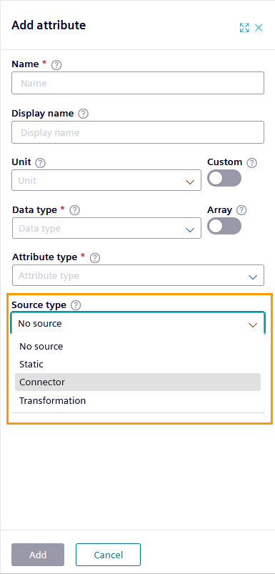
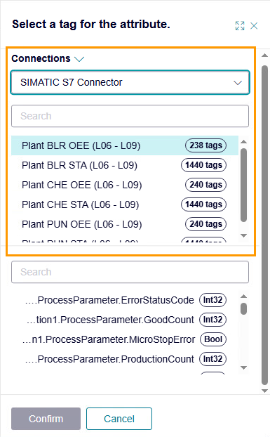
-
Under "Connector", select your connector and the corresponding connection. IIH Essentials lists the connector's tags at the bottom of the panel.
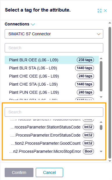
-
Select the tags from the list that you wish to collect and store in IIH Essentials.
-
Click "Confirm". IIH Essentials adds the information from the tag to the "Add attribute" view.
-
If required, change the "Name" and "Display name" of the tag.
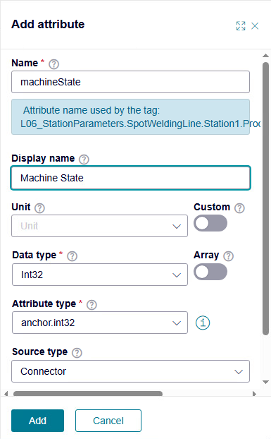
-
Click "Add". IIH Essentials adds the tag to the asset.
- Repeat steps 2–8 to add more tags.
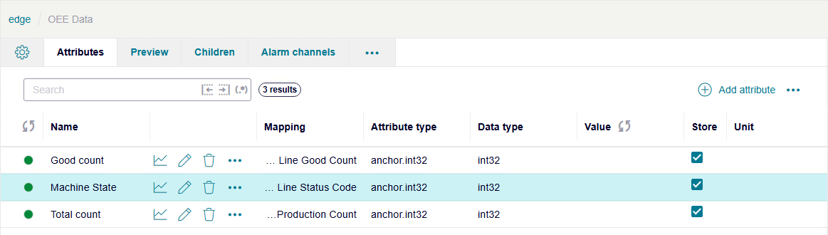
IIH Essentials lists the added tags and their values on the IE Device's "Attributes" page.
What's next?
You have successfully set up Industrial Edge, connected it to your environment, and prepared the asset model so that you can start implementing your use cases.